Boring heads are frequently utilized in machining operations for creating precise and accurate internal bores in workpieces. However, setting up a boring head is not a piece of cake; it involves essential steps like installing the head on the machine spindle correctly, choosing the most suitable boring bars and inserts, and deciding on the feed rates and speeds. The blog below will take you step-by-step through the boring head setup procedure.
Mounting on the machine spindle
- Before starting out, make sure the machine is turned off and the power source is unplugged. Additionally, ensure that you’ve put on the proper personal protective equipment like gloves and safety glasses.
- Next, look for any dirt, debris, or traces of previous operations on the machine’s spindle as well as the taper on the boring head. If necessary, carefully clean them with a lint-free cloth and a mild solvent.
- Thereafter, examine the boring head and machine spindle taper for damage. The precision of your machining could be impacted by any wear or damage indicators. If there are problems, think about getting them fixed or replaced.
- Once everything is checked and corrected, the next step is to firmly secure the boring head by fastening it to the machine’s spindle. Make that it is seated in the taper and properly aligned. To fasten it in place, use the drawbar or other suitable fastening devices. Follow the manufacturer’s instructions when tightening; exceeding them could cause spindle and head damage.
- After installation, check the boring head’s runout using a dial indicator. This step ensures that the boring head moves concentrically with the machine spindle. If necessary, modify the setup to reduce runout.
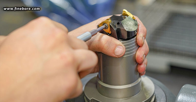
Picking the right boring bars and inserts
There are a number of factors you need to consider while selecting the boring bars and inserts; some of the most important ones mentioned below.
- Workpiece material: Take into account the workpiece’s material before you begin to machine it. Specific tooling is required for various materials. For instance, you need to use high-speed steel for softer materials and carbide inserts for harder ones.
- Bore size: Opt for boring bars with the correct diameter for the desired bore size. Make sure the boring bar has adequate length to extend to the appropriate depth.
- Toolholder type: The toolholder type on the boring bar should match the toolholder type on your boring head. Straight shank, Morse taper, and collet chuck are examples of the most common types used.
- Insert geometry: Choose inserts with the appropriate geometry for the type of cutting you’ll be undertaking. There are several typical insert geometries, including diamond, square, and round. For advice on particular uses, you may refer to the insert manufacturer’s recommendations.
- Cutting speeds and feeds: Calculate the cutting speeds (in surface feet per minute) and feeds (in inches per revolution), based on the material of the workpiece and the tooling that has been selected. For exact figures, you may consult cutting speed charts or employ a machining software.
- Tool coatings: If you want to extend the life of your tool and improve chip evacuation, especially when working with tough materials, think about employing coated inserts such as TiN, TiCN, or TiAlN.
Determining feed rates and speeds
- The majority of insert manufacturers offer suggestions for cutting data in their catalogues or online resources. These recommendations also include cutting speeds and feed rates for particular materials and insert types.
- Using the cutting speed, determine the required spindle speed by using the calculation “(Cutting Speed x 3.82) / Boring Bar Diameter”. Also, make sure your machine can turn at the calculated speed. Match the predicted spindle speed with the machine’s spindle speed. While manual machines may need manual tuning, modern CNC machines frequently offer automatic speed adjustments.
- Next, use the formula “(Spindle Speed x Chip Load) / Number of Inserts” to determine the feed rate. The insert manufacturer will normally offer the chip load information, or it can be estimated using the insert geometry.
- If you’re using a CNC machine, programme the proper feed rate into your CNC control software. For manual machines, you can use the feed rate controls to select the desired feed rate.
- Make a test cut on a scrap piece of material to make sure the feed rate and spindle speed are acceptable before beginning the main machining process. Make any alterations if required.
As you can see, having a right setup is just as crucial as purchasing a suitable, high-quality boring head if you want the internal bores of your workpieces to be exact and precise. Therefore, purchase your boring heads from prominent precision boring head manufacturers in Bangalore, one like Finetech Toolings, and then always follow safety precautions, review the manufacturer’s instructions for your specific equipment and tools, and follow the aforementioned guidelines to setup your boring head just right.