
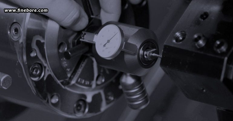
Precision micro boring requires substantially greater precision management compared to standard internal machining operations. When bore dimensions are minimal and specifications are stringent, cutting variables significantly affect tool bending, oscillation, thermal output, particle formation, surface quality, and ultimate bore dimension. A parameter selection that functions effectively for larger boring tasks may generate unreliable outcomes when applied to micro boring equipment. Consequently, cutting velocity, feed advancement, and material removal depth should be determined as an integrated strategy rather than as separate choices. The goal extends beyond rapid material extraction to establishing dependable cutting circumstances that guarantee consistent and reproducible outcomes. Material composition, bore dimension, tool stiffness, tool projection, cutting edge configuration, lubricant selection, and equipment performance capabilities must all be evaluated.
Why cutting parameters matter in micro boring
Micro boring bars are characteristically thin because they must access confined internal cavities. This characteristic renders them more vulnerable to cutting stresses and mechanical oscillation than conventional boring implements. Suboptimal parameter selection consequently impacts both implement durability and bore integrity. Inadequately chosen specifications may produce bore dimension inconsistency, vibration chatter, implement deflection, inadequate surface quality, accelerated cutting edge deterioration, restricted particle removal, and uncontrolled thermal buildup. The objective involves identifying an effective operating range where the cutting edge efficiently extracts material without straining the boring bar excessively. The fundamental parameters – velocity, advancement, and material removal depth – must be evaluated in conjunction with the stiffness, edge geometry, component securing, and complete setup of the micro boring equipment.
Selecting the right cutting speed
Cutting speed refers to the rate at which the cutting edge travels across the workpiece surface, typically measured in metres per minute. Within micro boring operations, cutting speed affects cutting temperature, tool wear, chip formation, and surface finish quality. Insufficient speed may promote built-up edge formation with certain materials, whereas excessive speed can generate additional heat and accelerate insert degradation. The optimal speed selection depends on workpiece material composition, insert grade and coating specifications, bore diameter dimensions, cutting-edge geometry characteristics, coolant application conditions, and desired tool longevity. A prevalent misconception is that increased spindle speed consistently enhances performance outcomes. In practice, speed must remain within the manufacturer’s recommended parameters for the insert and the overall micro boring system capabilities.
Setting the feed rate
Feed rate defines the advancement speed of the cutting edge through the workpiece material and is typically expressed in millimetres per revolution. This parameter directly impacts surface finish quality, cutting force magnitude, chip thickness, material removal rate, and tool lifespan. Excessive feed rate can elevate cutting forces and impose additional strain on a small boring bar, potentially resulting in vibration, deflection, or compromised bore geometry. Conversely, excessively low feed rate offers no inherent advantage. The cutting edge may experience rubbing rather than effective cutting action, producing unwanted heat generation and accelerating tool wear. The goal is to establish a feed rate that generates a controlled chip while preserving stable cutting conditions. Feed rate selection should also align with insert geometry specifications and workpiece material characteristics.
Determining the depth of cut
Depth of cut represents the volume of material extracted during each machining pass. In micro boring applications, this measurement typically remains considerably smaller than in rough boring operations, as the process frequently aims to refine or complete an already-existing hole. Raising the depth of cut amplifies cutting force and exerts additional stress on the boring bar. Consequently, precision micro boring typically employs regulated, modest cuts. Conversely, an excessively shallow depth of cut can introduce complications, as limited tool engagement may promote rubbing or inconsistent chip removal. The appropriate depth should facilitate sufficient tool engagement for optimal cutting-edge performance while adhering to the structural limits and specifications of the micro boring system and equipment.
Balancing speed, feed, and depth of cut
The three fundamental cutting parameters must not be refined in isolation. Adjusting cutting speed independently while keeping feed and depth of cut constant modifies the thermal and mechanical environment of the process. Similarly, raising feed rate can intensify cutting forces regardless of whether spindle speed changes. An effective optimization strategy must therefore evaluate cutting speed, feed rate, depth of cut, tool stiffness, material composition, and machine specifications as an integrated system. Should vibration emerge following a feed increase, merely decreasing spindle speed may not address the core issue. Similarly, an oversized bore may stem from tool deflection resulting from excessive cutting load rather than improper speed selection. Parameter optimization must pinpoint the genuine cause of instability before implementing targeted modifications.
How tool rigidity influences parameter selection
The structural rigidity of the micro boring bar establishes practical constraints on the cutting conditions that can be employed. A compact, rigid boring bar typically withstands greater cutting forces compared to an elongated bar featuring extended overhang. As overhang lengthens, the tool becomes increasingly vulnerable to deflection, chatter, dimensional inconsistency, and degraded surface finish. When extended reach becomes necessary, cutting parameters may require adjustment to preserve stability. Tool diameter, unsupported length, holder rigidity, and workpiece support must therefore be assessed before amplifying cutting loads. The tools should deliver adequate rigidity for the specified bore depth and diameter rather than depending exclusively on general cutting data.
Choosing parameters according to workpiece material
Workpiece material significantly affects the selection of appropriate cutting conditions. Aluminium and comparable non-ferrous materials may accommodate higher cutting speeds but can introduce complications regarding built-up edge formation and chip removal. Stainless steels generate substantial heat and may demand precise management of speed and feed rates. Hardened materials impose heightened requirements on insert durability and thermal stability. Consequently, cutting parameters should be determined according to the particular material specification rather than relying on broad material classifications. Insert manufacturers customarily supply recommended initial ranges for speed, feed, and depth of cut. These baseline values should subsequently be refined according to the specific machine characteristics, configuration, workpiece geometry, coolant application, and desired production outcomes.
Fine-tuning parameters for precision finishing
Micro boring is frequently executed as a finishing operation, where the final pass plays a critical role in determining bore accuracy and surface finish quality. During the finishing phase, the emphasis should be on managing material removal in a controlled manner rather than maximizing output speed. A stable and rigid tool setup, regulated cutting speed, suitable feed rate, minimal and uniform depth of cut, efficient chip removal, and dependable coolant supply all enhance overall results. Final parameters must be selected based on insert geometry and the manufacturer’s specified operating parameters. When finished bores consistently exceed tolerance limits, cutting parameters should be examined in conjunction with tool wear, spindle runout, thermal conditions, machine precision, and the overall condition of the boring kit.
For precision micro boring applications, choosing appropriate tooling is as critical as fine-tuning cutting parameters. FineTech Toolings provides specialized boring solutions engineered to support precise internal machining, stable cutting operations, and uniform bore quality. The micro boring kit enables manufacturers to achieve dependable performance in applications requiring strict tolerances and superior surface finishes.
Optimizing cutting parameters for micro boring involves less about identifying a single universal speed, feed, or depth of cut and more about creating a balanced interaction among these variables. Since micro boring bars typically feature slender designs, even modest variations in cutting forces can influence vibration, tool deflection, surface finish, and dimensional accuracy. Cutting speed affects heat generation, tool wear, and production rate, whereas feed influences cutting forces, chip formation, and surface finish quality. Depth of cut controls material removal rate and tool stress. These parameters must be aligned with workpiece material, insert geometry, tool stiffness, machine capacity, and tolerance specifications. Beginning with manufacturer-provided recommendations and implementing systematic modifications enables a micro boring kit to deliver stable cutting, foreseeable tool longevity, and consistent bore quality.